Analysis of Working Principle of Card Punching Machine and CCD Visual Alignment Technology
blog 2026-07-22 23:38:53 128
The working principle of the card punching machine is to use an automatic feeding system to convey the sheet or roll materials (such as PVC, paper or composite materials) to the positioning station. After the positioning system locks the target area, the die is driven by servo or hydraulics to obtain high-precision shear separation.
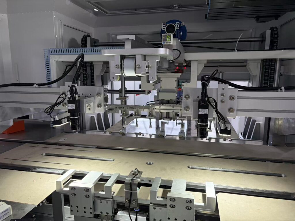
The core of modern high-precision card punching machine is CCD visual alignment technology. The system obtains the printed mark points (Mark points) on the material through industrial camera, and the image processing software calculates the deviation between actual position and ideal position on X axis, Y axis and rotation angle (theta). And then the high-precision XY theta alignment platform is driven to perform micrometer-level physical compensation, finally achieving punching accuracy up to $\\pm0.02 \ \text{mm}$ to $\\pm0.05 \ \text{mm}$, completely solving the eccentricity and white edge problems caused by printing stretching deformation in traditional mechanical positioning.
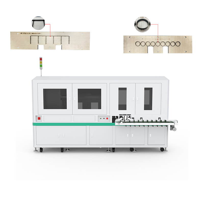
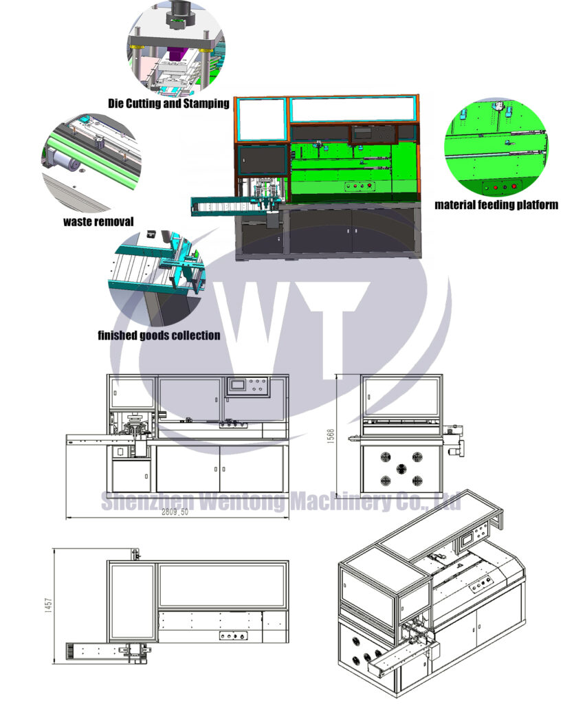
1.Basic workflow and core components of a card punch machine
Card punching machines (often called “punching machines” in the industry) are important process equipment for determining the appearance quality and dimensional accuracy of products in the automated production lines of smart cards (such as IC cards and ID cards), game playing cards and special industrial filter paper.
[ Automatic feeding ] ➔ [ Optoelectronic/sensor detection ] ➔ [ CCD camera takes Mark points ] ➔ [ Deviation calculation and alignment platform compensation ] ➔ [ Mould punching ] ➔ [ Material collection and waste disposal ]
1.1 Five steps from automatic feeding to finished product collection
- Automatic feeding: Material is smoothly fed into the punching area in the form of a sheet or roll, by a suction cup or belt mechanism.
- Sensing & Imaging The sensor checks the position of the material, while the CCD industrial camera turns on the light source and takes high-precision images of the area to be inspected.
- Coordinate calculation and compensation (alignment): The system algorithm compares image pixels, calculates the offset, and fine-tunes the platform to achieve precise alignment within milliseconds.
- Punching Under the driving of the power system, the upper die falls and forms a small gap with the lower die to cut out and complete the punching of the card shape or internal hole position.
- Stacking & Sorting: Punched, finished cards drop into the card pocket. The receiving mechanism automatically rolls or strips off the waste edges and corners.
1.2 Three major physical factors that affect cutting accuracy
Stamping die material and clearance The sharpness of the die edge and the clearance between the upper and lower dies are directly related to the presence of burrs on the punching part.
Stability of power drive: Uniformity of pressure of servo motors or hydraulic systems at the time of downstroke.
The sensitivity of the positioning and alignment mechanism is the speed of response, the repeatability accuracy of the adjustment of the physical position of the material to the ideal coordinates.
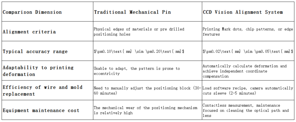
2.Positioning technology evolution The evolution includes traditional mechanical positioning and CCD visual alignment methods. mechanical positioning and visual CCD alignment.
As the market demand for card appearance alignment increases, the positioning method of card punching machines has undergone a major technological leap from “extensive mechanical contact” to “non-contact optical perception”.
2.1 Limitations of Conventional Mechanical Pin Position
Conventional card punching equipment uses either material edge alignment or pre-drilled physical positioning holes (pinholes). This method has been used in the past, but obvious bottlenecks are present when facing with modern complex processes:
Accumulated printing error: The mechanical positioning pin cannot sense the relative displacement between the printed pattern and the edge, and the material will undergo irregular small stretching deformation in the process of hot pressing, laminating or printing.
Physical wear: The pin will wear down and can easily cause edge deformation over time due to the impact of the pin against the material edge.
Complicated mould replacement and adjustment: When replacing cards of different sizes or layouts, the position of the positioning pin must be repeatedly manually and mechanically adjusted, which is time-consuming and labor-intensive.
2.2 Improvements of the technology of the CCD visual alignment system
The CCD industrial visual alignment system has completely changed the logic of alignment. It is no longer dependent on the physical edges of the material. It directly “sees” the printed patterns or designated mark points on the material.
In high-end manufacturing environments, the use of industrial-grade, high-precision punching machines with CCD systems can reduce the scrap rate caused by material printing stretching by more than 80%.
Table. Multi-dimensional comparison of mechanical positioning and CCD visual positioning
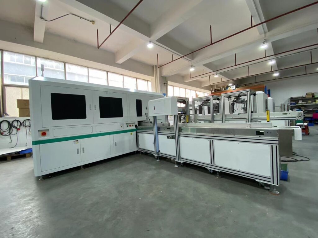
3.Deep Disassembly Working Principle of CCD Visual Alignment System
The CCD visual alignment system is not a single-point measurement but a closed-loop control system, which comprises optical imaging, computational power analysis, and mechanical compensation.
Industrial CCD camera + special lighting source
│ (Image Data)
▼
[Visual processing control software] Calculate the difference (Δ X, Δ Y, Δ θ).
│ (Movement command)
▼
High-precision X-Y-θ servo alignment platform with physical displacement compensation and execution punching.
3.1 Light source and camera acquisition mark point (objective)
The system is normally equipped with 2-4 industrial CCD cameras with high resolution. The choice of the light sources (axial, ring, backlight, etc.) is very important to obtain high contrast images between the target (mark point) and the substrate background. Common mark point forms are crosshairs, solid circles, concentric circles or certain squares.
3.2 Image processing algorithm and coordinate deviation calculation
After the camera stops shooting, the visual software will perform the following mathematical operations in milliseconds:
Image Binarization and Edge Extraction: Noise filtering and Determining the Geometric Centre Pixel Coordinates of the Marked Points.
Coordinate System Conversion Convert pixel coordinates to the real physical world coordinate system of the machine (mm).
Deviation matrix solution Compare current captured coordinate with target standard coordinate, and get the deviation values of three degrees of freedom by inverse kinematics:
Horizontal translation
Vertical offset
Rotation angle (deflection angle) offset
3.3 Microscale physical compensation mechanism of multi-axis servo/alignment platform
Once the deviation data is received by the control system, it immediately sends commands to the high-precision alignment platform (e.g., the diagonal three-axis servo or UVW platform). The platform performs translation and rotation movements in milliseconds based on the calculated reverse offset to precisely “transport” the material to the point where the absolute perpendicularity of the upper die edge is reached, and then the servo punch drops quickly to complete the cutting.
4.Application of CCD Visual Punching Machine to Various Materials and Industries
The physical properties of different materials determine different configurations of visual positioning parameters and punching moulds.
4.1 Smart card (PVC/ABS/PET) and chip locati0n
The manufacture of smart cards (e.g. financial IC cards, public transport cards, etc.) is generally a multi-layer PVC hot pressing assembly process, which easily causes plastic layer shrinkage. The CCD system can directly identify the grooves or exposed chips (contactless/contact chip) on the card core, ensuring that the distance between the punched outer frame and the centre of the chip strictly complies with ISO standards.
4.2 Game cards and playing cards (paper/plastic) pattern edge compensation
The symmetry of border patterns is extremely high in trading card games. If the border cutting is eccentric this will directly affect the market value of the card. The CCD vision system can directly capture the corners of the printed border of the card, and can perform the independent translation and angle correction on a single sheet and have the same width of the surrounding border.
For the punching performance and mould loss of the multi-layer materials in the punching process, please see the detailed analysis on the punching characteristics of PVC and PET smart card substrates. Further reading:
4.3 Attempt to match unmarked points between special industrial filter paper and composite materials.
For example, for industrial filter paper or non-woven fabric punching without printed mark points, advanced CCD systems can directly find the physical outer edges or pre-punched positions of materials through “contour recognition algorithms”, and realise the balance of high flexibility and advantages of non-contact alignment.
5. Risks of accuracy, limitations and tuning of maintenance in factory operations
Even though the CCD visual alignment system is very good, in the actual factory production environment, neglecting the environmental and maintenance details may still cause alignment failure or reduced precision.
5.1 Light source attenuation and ambient light interference
- Risk: The industrial LED light source may age with time, or the illumination may be changed by strong light or direct sunlight at the top of the workshop, so that the camera cannot recognise the boundary of the mark point.
- The light shield should be located in the visual inspection area and powered by a constant current light source. Use a calibration board to periodically calibrate the grey scale value of the camera.
5.2 Limits to thermal expansion, contraction and tensile deformation of materials in printing
- Limitations: The CCD vision system can compensate for translation ($\Delta X$, $\Delta Y$) and overall rotation ($\Delta \theta$), but can not change the non-linear tensile deformation of the material itself (such as the left side of the entire material elongates by 0.5mm while the right side does not elongate).
- Reminder: When the printing scaling ratio is seriously distorted and exceeds the set tolerance threshold, the equipment should alarm and stop printing to avoid wasting substrate.
5.3 When is professional engineers’ intervention in calibration required?
It is recommended to stop adjusting parameters by yourself and contact the equipment provider or professional engineering personnel when the following situations happen:
- The calibration data file of the visual system This is caused by a damaged calibration data file in the visual system, which leads to a mismatch between the camera pixels and the mechanical coordinates.
- Due to the mechanical clearance or ball screw wear of the XY-θ motion platform, the physical displacement of the XY-θ motion platform is inaccurate after the compensation command is issued.
- If the mould is worn seriously, the wire drawing and burrs will appear on the edges after punching (at this time, the visual accuracy can not improve the quality of the shear section, no matter how high it is). You can start with the basic maintenance by looking at the daily maintenance and wear inspection guide for stamping dies.

6.Common operational errors to avoid
- Error 1: Using mark point designs from different batches/colors. The camera misjudged due to the printing layout being changed without synchronising the update of the target template in the visual software.
- Error 2: Forgetting lens optical contamination. The CCD lens is not regularly cleaned with a dedicated dust-free cloth and isopropanol to remove the tiny paper scraps or PVC dust generated by punching.
- Error 3: Increasing the compensation speed without thinking. When the acceleration of the alignment platform was set too high, the mechanical vibration was so large that the vibration started to decrease before the vibration subsided. This led to the reduction of the actual alignment accuracy.
7.Related guides & Further reading
Solution of industrial grade high precision punching machine & automated production line
Stamping Die Daily Maintenance and Wear Inspection
Smart card substrates made from PVC and PET and their cutting properties
8. FAQ Frequently Asked Question
Q1: Is a CCD visual card punch machine faster or slower than a normal mechanical punch machine?
CCD visual punching machines have a slightly longer cycle time than fixed mechanical blocks due to the addition of the process of “photography calculation platform compensation” in a single punching action. However, from the perspective of comprehensive production capacity and yield rate, CCD visual punching machines do not require frequent shutdown and manual correction, and the scrap rate is reduced to an extremely low level. Therefore, the actual comprehensive effective production capacity (OEE) is far more than that of the traditional equipment.
Q2: When there is no Mark dot printed on the surface of the material, is the CCD visual positioning system still able to work?
Answer: Sure. Modern CCD systems have many different positioning modes. When there is no mark point, the system can be converted into “pattern contour positioning” or “feature corner positioning” mode, and the punching features or edge lines on the card can be located via backlight detection.
Q3. What is the compensation limit of the CCD vision system for tolerances in printing?
In general, the physical compensation range of the servo alignment platform is usually between $\\pm2.0 \ \textmm$ and $\\pm5.0 \ \textmm$, and the angle compensation is about $\pm2^\circ \ \sim \pm5^\circ$. If the printing stretch or deviation exceeds this limit, it indicates that the previous printing or composite process suffers from a serious defect and the system will generate an out-of-tolerance alarm.
Q4: Does ambient temperature impact the accuracy of visual alignment?
Answer: It does matter. Severe temperature changes cause thermal expansion and contraction of plastic substrates (e.g., PVC) and also micrometer-level thermal expansion of industrial camera brackets. Therefore, in high-precision card cutting workshops, it is recommended to maintain a constant temperature and humidity environment (temperature $22 \pm 2 ^ \ \circ \text {C} $, humidity $45 \ -65 \% $).
9.Summary
So the industry of automatic card manufacture has to abandon the traditional mechanical positioning of the card-punching machines and switch to the CCD visual alignment in order to enhance the quality and the production capacity. The entire closed loop of “industrial camera acquisition algorithm millisecond calculation multi-axis platform physical compensation” has successfully overcome the industry challenges of printing deformation and cumulative errors through CCD vision technology. In actual production, correct understanding of its working principle and proper optical and mechanical maintenance are the core guarantees for the factory to maintain a stable and high yield rate.
Author: Huang Jianwen, Director of Wentong Technology Department